Choose an integrated LPR terminal when one mounting location can satisfy both plate capture and driver communication, and the supplied configuration meets your operating and service needs. Choose a separately mounted ANPR camera when the best camera position differs from the best display position, or when retaining and replacing equipment independently is important. Neither form is automatically more accurate, cheaper or easier to maintain. The useful comparison is between two complete lane configurations at your site.
This guide is for distributors, parking integrators and project buyers choosing between a camera-and-display terminal and a separate camera arrangement. It focuses on physical layout and ownership costs. Recognition software, permission decisions, barrier control and safety equipment still need their own defined scope.
1. Define what each quotation actually includes
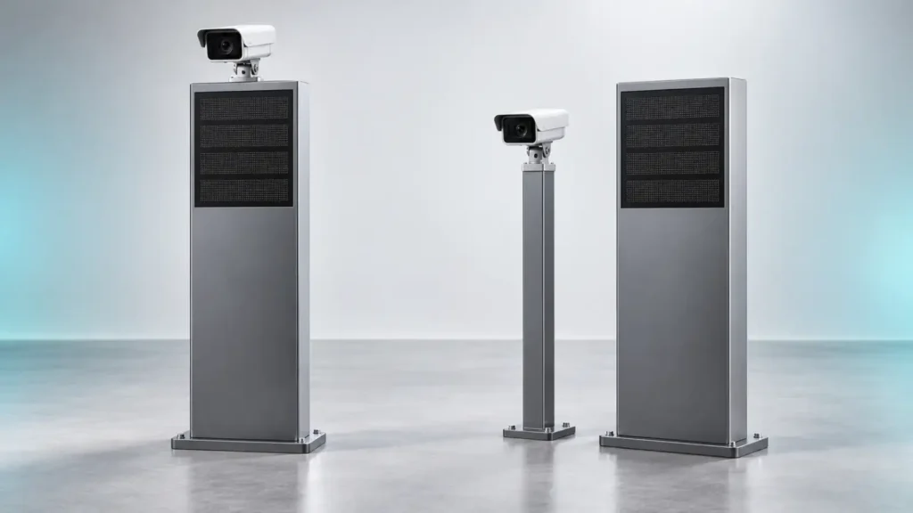
An integrated LPR display terminal combines a recognition camera and a driver-facing information display on a common pedestal or assembly. Depending on the model, it may also include illumination, a speaker or other modules. The word “integrated” does not identify the processor, power arrangement, supported software or replaceable parts.
A standalone ANPR camera is a camera mounted independently of that display assembly. It may perform recognition onboard or use separate recognition software. “Standalone” describes the physical product here; it does not mean that access decisions, billing and operation during a network failure are all handled autonomously.
If the driver needs messages, a camera-only quotation must include a suitable display and its control path, or identify an existing display that can be reused. If no display is required, adding a terminal simply to obtain recognition may add equipment without solving another driver or operator need.
For the SHUNJIE options, start with the ALPR display terminal and ANPR camera product pages. Request drawings and a configuration list for the proposed versions. A product-family page is a starting point for this comparison, rather than a complete bill of materials.
2. Check two different views: the plate and the driver
The camera needs a usable view of the required plate as the vehicle approaches or passes the capture point. The driver needs to see and understand the intended message at the point where a decision or action is needed. These two viewing tasks can favour different positions.
Axis’s license plate capture white paper explains how mounting height, lateral position and capture distance affect viewing geometry. It also distinguishes a camera’s overall resolution from the detail actually available across the plate. This is why moving an assembly to make its display more visible can change the capture conditions. The proposed camera’s own installation requirements remain the basis for the design.
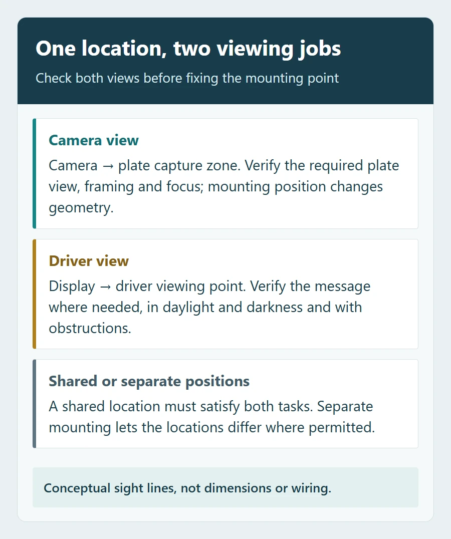
Mark the capture zone and normal stopping position on a site sketch before selecting the pedestal location. Record the approach path, bend, island edge, likely queue position and any obstruction. Identify whether the required plate is at the front or rear for the actual vehicles and jurisdiction. A design for an approaching front plate should not be assumed to work for a rear-only requirement.
Then check the message from the driver’s normal seat position for the relevant vehicle types. Can it be read before the driver needs to act, without leaning out or looking away from the intended route? Could another vehicle, a barrier cabinet or a queued vehicle obscure it? Assess direct sunlight, darkness, reflections, text size, language and message length in the proposed location.
An integrated terminal can be a practical choice where both views work from the available island. Some terminals provide camera adjustment within the assembly; do not assume the camera is fixed. However, angular adjustment does not move the pedestal to a different place. Ask the supplier to mark the actual adjustment range and demonstrate the resulting image while the display remains correctly oriented.
If that arrangement requires a compromise in either view, compare a separate camera location with a display positioned for the driver. Separation offers placement options; it still needs a permitted mounting point, suitable cabling and a design that can be commissioned and maintained.
3. Compare the complete lane, not the enclosure count
Use this table to identify the evidence each option needs. The entries describe possible advantages and checks, not guaranteed characteristics of every product in a category.
| Decision | Integrated terminal | Separate camera arrangement | Evidence to request |
|---|---|---|---|
| Camera and display position | A common assembly may suit a compact island if both viewing tasks work. | Camera and display can be located independently where mounting is permitted. | Marked capture and driver views; actual adjustment and mounting drawings. |
| Existing equipment | May replace or duplicate an existing display; confirm the intended scope. | May retain a suitable display, pole or controller if compatibility and condition are verified. | Reuse list, supported display commands and condition survey. |
| Installation work | Some interconnections may be internal to the assembly; external services still need provision. | Separate mounts and cable routes may be needed; existing infrastructure may reduce new work. | Full cable and foundation schedule, supplies, network equipment and exclusions. |
| Fault and repair scope | Modules may be serviceable separately, or a fault may require a larger assembly to be removed. | A camera or display may be replaced separately, but shared power or software can still affect both. | Service drawing, replaceable modules, shared dependencies and recommissioning tasks. |
| Future changes | Expansion depends on the assembly, controller and supported software. | Independent mounts can help relocation, but a new device still needs compatible interfaces and licences. | Documented upgrade path for the specific future requirement. |
| Total cost | Compare the supplied assembly, civil work, integration and spare strategy together. | Include any separate display, mounts, integration, installation and support. | Equal-scope quotation and the cost of an agreed replacement scenario. |
What “less wiring” leaves unanswered
A shared pedestal can reduce some field connections between its own modules. It does not remove the need to specify power, network or communication paths, barrier connections and any separate detection equipment. Ask which connections are factory completed and which must be installed locally.
Compare the routes that will actually be built. A separate camera on an existing usable pole may require less new civil work than a new pedestal location; at another site, one common mounting point may be simpler. Include access for cable inspection, weather sealing, cleaning and service-door opening. Keep equipment and maintenance access clear of the vehicle route, pedestrian route and barrier movement envelope.
A display that provides information is also different from a payment or user-input device. Showing a fee or a QR image does not establish that payment acquisition, transaction confirmation or an accessible assistance route is included. Define those functions separately when they form part of the project.
4. Ask what must stop when one part needs repair
Do not assume that an integrated terminal must be replaced as one piece, or that separate products are automatically fault independent. The meaningful questions concern the actual modules, shared services and supported repair procedure.
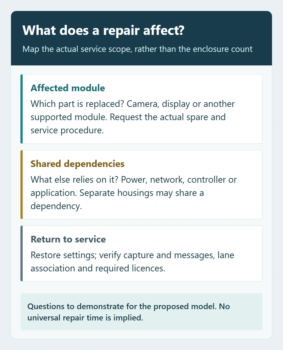
For example, ask the supplier to explain a display failure. Can the camera still report observations? What will the driver see, and which controlled operating procedure applies while messages are unavailable? Can a trained local technician replace the display module, or must the terminal return for service? The answers may differ between models that look similar.
Repeat the exercise for a camera failure and a shared power-supply fault. In a separate arrangement, a common supply, network switch or application can still interrupt several components. Physical separation alone does not establish resilience.
For each replacement, list the spare part or assembly, required technician, settings backup, licence transfer conditions and tasks before return to service. A camera replacement may require alignment and recognition checks; a display replacement needs its content and lane association checked. Agree which records are required to show the repair is complete. Do not infer a repair time from the number of boxes.
Compare these costs over the same planning period: initial equipment, mounting and civil work, field cabling, integration, licences, commissioning, spare stock, service visits and the operational impact of the agreed outage. Keep prices and response commitments tied to the actual quotation. A lower purchase price cannot settle the comparison when the two offers exclude different work.
5. Use your site constraints to narrow the choice
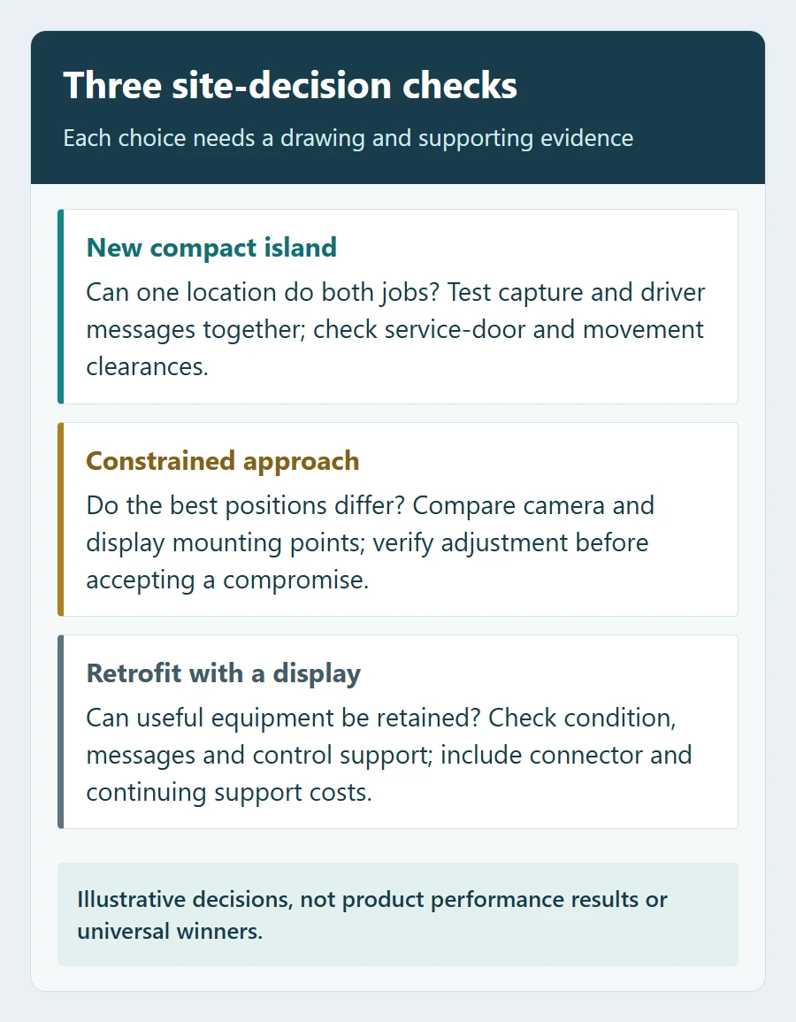
A new compact entry with simple driver messages: an integrated terminal is a reasonable candidate when the camera view and message view both work from the island. Confirm the service clearance and full connections before treating the compact appearance as an installation saving.
A curved approach or an awkward stopping position: compare separate mounting points first if the best capture location is away from where drivers need information. Ask whether the proposed terminal’s adjustment can solve the actual geometry; do not reject or accept it solely from a catalogue photograph.
A retrofit with a useful display already installed: survey its condition, legibility, supported messages and control method. A separate camera may allow reuse. Include connector work and ongoing support in the quotation before counting the retained display as a saving.
A lane with mixed vehicle heights or changing requirements: test the relevant viewing positions and maintenance access. If a future display move or camera relocation is likely, request an upgrade proposal for that change. Do not buy extra modules on the assumption that any camera or display can be substituted later.
6. Demonstrate both jobs before approving the configuration
Use the exact proposed camera, lens, terminal or display, software and firmware configuration. Agree the test vehicles, plate requirements, lighting conditions and acceptance criteria first. The following is a suggested buyer demonstration plan, not a report of completed tests.
| Demonstration | What to check | Record to keep |
|---|---|---|
| Capture from the proposed location | The required plate is visible and readable along the intended approach; verify representative day and night conditions. | Marked location, configuration, permitted sample images and recognition output. |
| Message at the decision point | Relevant drivers can read the actual message in time to act; check language, glare and obstructions. | Viewing position, displayed content and observed limitations. |
| Correct message for the correct lane | An accepted, denied or unresolved result produces the intended message; a displayed instruction does not falsely imply the barrier has moved. | Correlated result, message and observed lane state. |
| One module or dependency unavailable | The supplier explains and, using an approved method, demonstrates the specified affected functions and controlled exception route. | Dependency diagram, observed behaviour and recovery requirements. |
| Replacement and recommissioning | The proposed spare and service process restore configuration, capture alignment and correct display association. | Replaceable part, responsible party, backup and repeated checks. |
Record unresolved items with an owner before committing to the order. A bench demonstration can check messages and service procedures, but it cannot reproduce every physical visibility condition at the finished site. Confirm those conditions during commissioning. Recognition, information display and permission logic also do not replace the barrier’s approved safety controls.
Prepare a configuration enquiry that can be compared
Send the suppliers the same short brief:
- Entry and exit photos, a dimensioned lane sketch, approach direction, stopping point and permitted equipment locations.
- Relevant vehicle types, front or rear plate requirement, operating speed and representative lighting conditions.
- Messages drivers need, language, viewing point, and whether information, user input, payment or assistance is required.
- Existing camera, display, barrier controller, power, network and software models that you want to retain.
- Required service access, local repair capability, spare strategy and the future change you want the design to accommodate.
- Two equal-scope proposals with drawings, included work, exclusions and the demonstration evidence above.
For broader equipment boundaries, the LPR parking system component guide can help organise the brief. Ask SHUNJIE to assess both physical arrangements against your site information and confirm the exact supplied configuration. The stronger choice is the one that can demonstrate both a usable plate view and clear driver communication, with an installation and repair scope your team can support.
Featured image: AI-generated equipment concepts for comparing physical arrangements. Not actual SHUNJIE models, scale drawings or a completed installation.
Featured image: AI-generated equipment concepts for comparing physical arrangements. Not actual SHUNJIE models, scale drawings or a completed installation.