An inductive loop, sometimes called a ground sensing coil, gives an LPR parking system information about a vehicle in a defined lane area. Together with its detector module, it may trigger image capture or provide a vehicle-presence signal to the controller. These roles must be specified separately. Detecting a vehicle does not establish pedestrian protection or the safety of the complete barrier installation.
This guide explains the planning and installation sequence: site assessment, loop layout, turns, feeder routing, pavement work and commissioning. It is a coordination guide for a qualified installer, not a universal wiring or cutting specification. Use the actual detector and barrier manuals, the approved site design and the required professional assessment before work starts.
Why the Ground Sensing Coil Matters
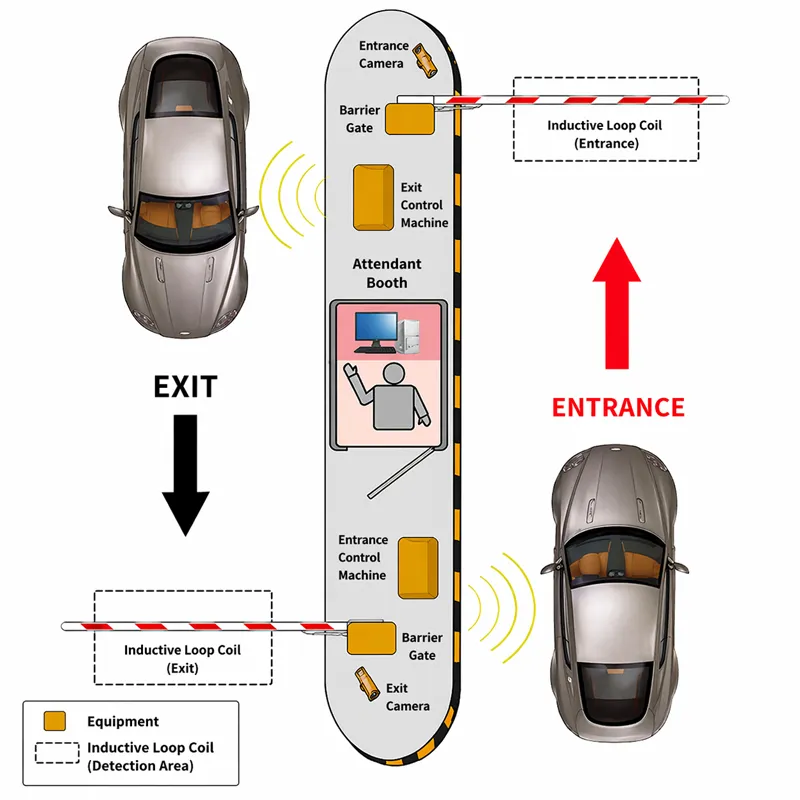
The loop’s position and assigned function determine what the controller learns. A capture trigger must relate to the camera’s usable plate-reading area. A vehicle-presence input must remain appropriate while the vehicle occupies its specified zone. Detector mode, controller logic and the response to a loop fault all need agreement; a successful plate read does not verify these functions.
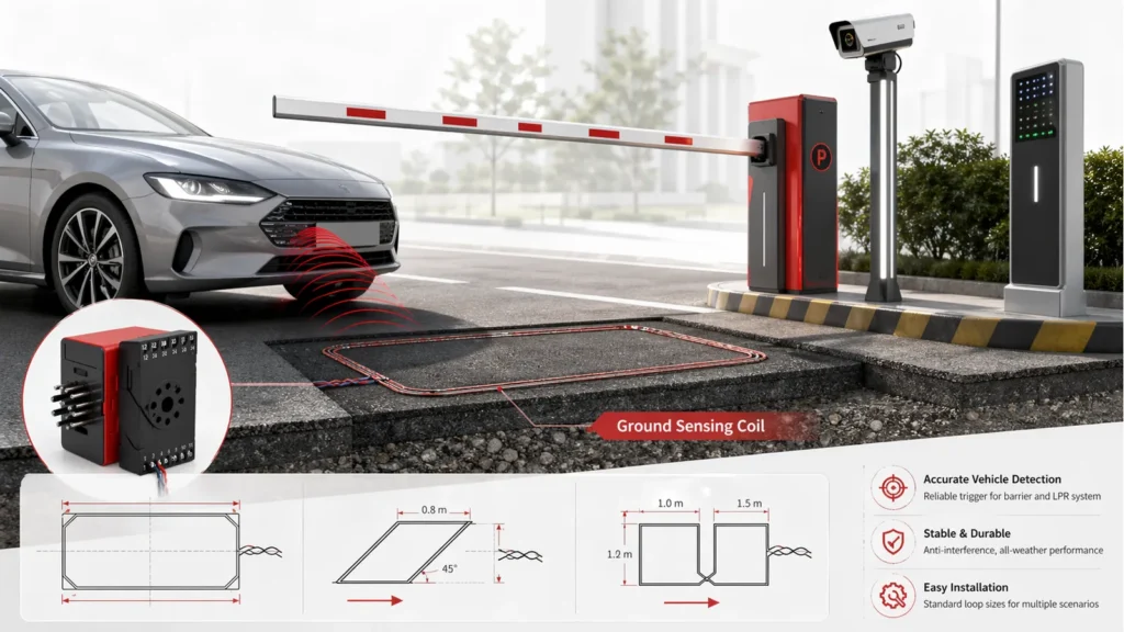
The existing entrance-and-exit drawing illustrates component positions, not an approved layout for every site. The number of loops, detection coverage and protective equipment must be designed for the actual lane. Never bridge a protective input to compensate for a poorly installed or faulty loop.
1. Check the Installation Site
Before pavement cutting or cable laying, identify the equipment, obtain its current installation documents and confirm the lane function. The following checks help the installer decide whether a buried loop is suitable and what further design information is needed.
Basic site checks
- Assess pavement condition, joints and cracks. A moving or deteriorating surface can damage the loop and its seal.
- Identify metal covers, drainage grates, buried metal and nearby moving gates. Their effects and required separation depend on the actual geometry and detector.
- Locate electrical services and interference sources. Plan the feeder route and electrical separation under the applicable equipment instructions and site requirements.
- Confirm the location of reinforcement, utilities and any post-tensioning. Do not cut an unknown slab; obtain the necessary survey and structural approval first.
- Consider neighbouring loops and detectors. Channel assignment, frequency selection and separation need a coordinated plan to manage interference.
- Define the vehicles to be detected, including motorcycles or high-clearance vehicles if relevant. Test requirements must include their actual paths through the lane.
- Plan traffic exclusion, safe work access, suitable cable and sealant, and cleaning of the approved groove before laying cable.
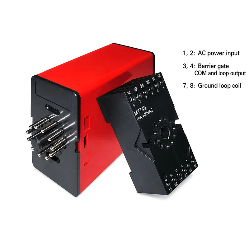
The existing terminal illustration is an unidentified equipment example. Its pin numbers and AC-power labels must not be used as a wiring diagram for your detector. Supply type, voltage, socket, relay rating and controller input must be verified from the exact model documents by a qualified person before connection.
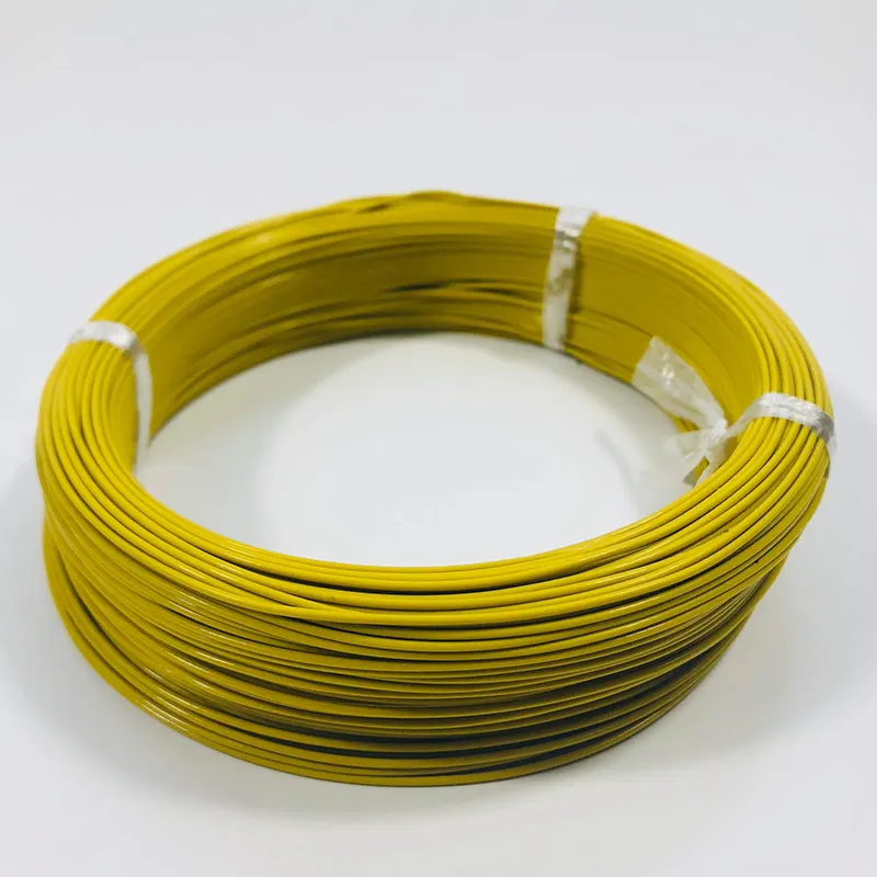
Site planning reference
| Item | What must be confirmed | Why it matters |
|---|---|---|
| Metal and reinforcement | Actual position and equipment-specific design allowances | Affects the detection field and loop behaviour |
| Electrical services | Survey, segregation and permitted feeder route | Avoids unsafe cutting and reduces interference risk |
| Adjacent loops | Channel, frequency and separation plan | Reduces unwanted interaction between detectors |
| Pavement and structure | Condition, permitted cutting and approved groove detail | Protects the structure and the cable installation |
| Vehicles and lane use | Required vehicle types, paths and detection roles | Defines coverage and commissioning tests |
| Groove preparation | Cleanliness and moisture conditions required by cable and sealant | Helps avoid damaged insulation and poor sealing |
2. Choose the Loop Layout
Different lanes require different geometry. Rectangular, angled and specialised arrangements are design options, not interchangeable recipes. The loop dimensions must suit the detection zone, vehicle types, available pavement and the selected detector’s requirements.
2.1 Rectangular layout
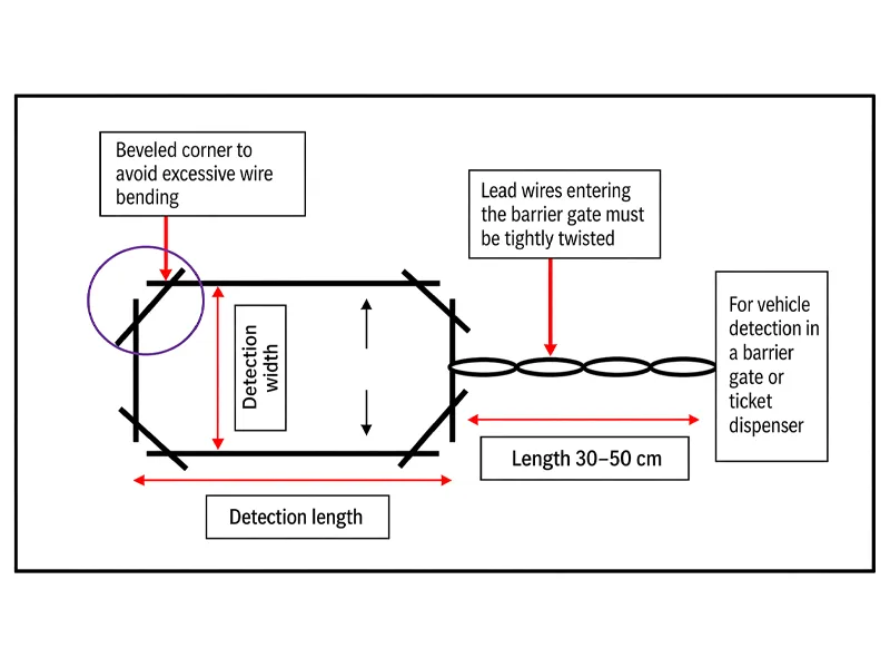
A rectangular loop is commonly used for vehicle lanes. Its orientation, width and length must match the intended vehicle path and detector guidance. Avoid adopting a fixed road-edge clearance or distance between sides from a generic article.
Corner treatment should prevent damaging the cable insulation and respect the cable’s permitted bend. The existing drawing shows a possible arrangement with bevelled corners; its printed dimensions are illustrative and are not the approved cutting dimensions for this project.
2.2 Angled layout
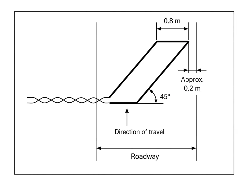
An angled layout, such as the existing 45-degree illustration, may be considered where the selected detector documentation and site design support it. Do not assume that changing the angle guarantees motorcycle or bicycle detection. The required vehicle samples and likely riding paths must be included in controlled commissioning tests. The drawing’s dimensions are examples, not universal requirements.
2.3 Special layouts and wider lanes
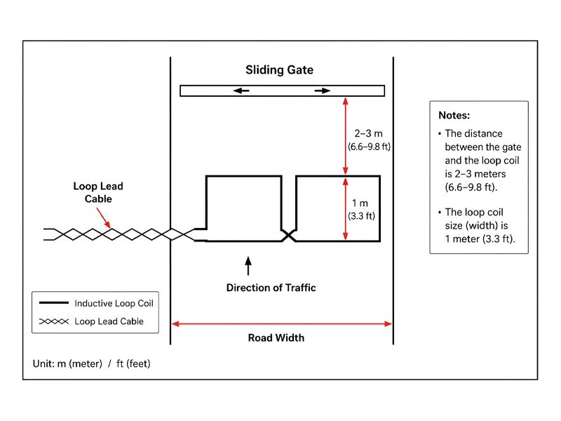
Wide lanes, unusual vehicle clearance or moving metal structures can require a different geometry, multiple loops or a different detection method. A figure-eight layout should only be used where the equipment guidance and specialist design support that arrangement; lane width alone is not a sufficient selection rule.
The retained image is a sliding-gate loop layout example, not proof of a figure-eight arrangement. Its printed clearances are not transferable to every parking barrier. Review the actual gate movement, buried metal, detection coverage and controller function before deciding on the layout.
Compare layout decisions
| Layout | Possible use | What to verify |
|---|---|---|
| Rectangular | Defined vehicle paths in a parking lane | Dimensions, orientation and detection zone |
| Angled | Special vehicle or path requirements | Manufacturer support and actual vehicle tests |
| Special or multiple-loop arrangement | Wider coverage or difficult site conditions | Detector compatibility, interaction and controller logic |
3. Set the Number of Turns for the Actual Detector
Loop geometry, turns, feeder and nearby metal together affect the circuit presented to the detector. Use the detector’s specified operating range and approved design method. There is no universal inductance target or perimeter-to-turns table that applies to every unit.
Determine the initial winding from the actual manufacturer’s instructions, then record the installed measurements using suitable equipment and the prescribed test method. A measured value within a stated range is only one check; it does not prove adequate vehicle coverage, stable presence detection or protective-system performance.
Turn-count decision record
| Record | Required basis |
|---|---|
| Detector model and revision | Exact manual and supported loop requirements |
| Loop geometry and turns | Approved layout and manufacturer design method |
| Feeder length and routing | Actual installed route and cable specification |
| Electrical measurements | Prescribed test method and acceptance limits |
| Vehicle test results | Agreed vehicle types, positions and control behaviour |
If readings or performance are unacceptable, identify the cause before changing turns. Nearby reinforcement, damaged insulation, a loose feeder, an unsuitable connection or the detector configuration may be involved. Changes should remain within the approved design and be followed by repeat measurements and functional tests.
4. Route the Loop Feeder Correctly
The feeder connects the buried loop to the detector. It is distinct from the detector’s relay output to the controller. Keep these functions clear in the drawings and labels so the loop cable is not mistaken for a power or control-output connection.
Feeder planning rules
- Plan enough continuous cable for the approved loop and route. Avoid unnecessary joints; any permitted joint needs the specified protection and a recorded location.
- Use the feeder pairing or twisting specified for the actual detector and cable. The required construction and twist rate must come from its documentation.
- Check the permitted feeder length and routing. Do not apply a universal maximum from an unrelated product; longer routes can affect the overall loop characteristics.
Why feeder stability matters
Uncontrolled conductor movement, poor joints and unsuitable routing can cause intermittent behaviour. Support and protect the feeder as specified, separate it from incompatible circuits and label the ends. Wiring, earth arrangements and electrical tests belong to qualified personnel using the correct equipment documents.
5. Embed and Commission the Loop
Pavement work should start only after the site survey, approved layout, service checks and safe working arrangements are complete. The original illustrations show examples of slot construction; their printed width, depth and layer details are not authorisation to cut an unknown pavement or connect mains power.
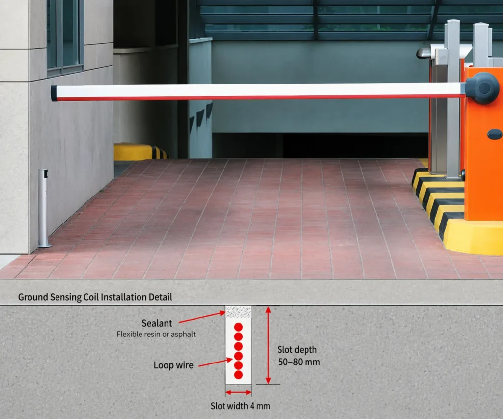
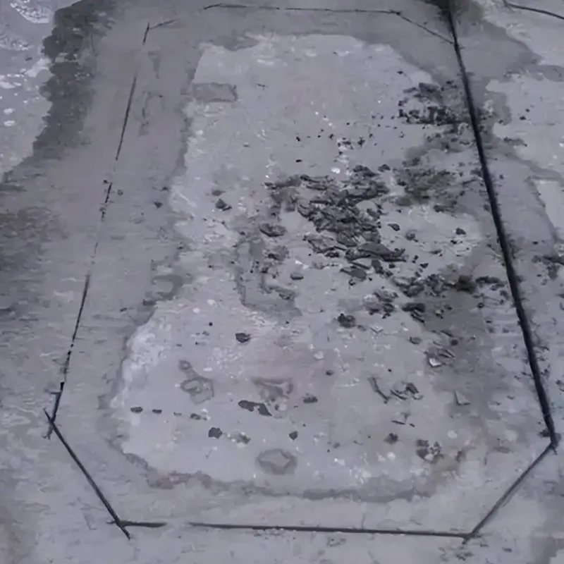
Confirm the groove detail before cutting
Agree the slot width, depth, corner treatment and feeder route from the approved civil detail, cable bend limits, sealant requirements and equipment instructions. Structural slabs and buried services need specific assessment. Do not increase cutting depth or cut reinforcement simply to fit a generic loop diagram.
Installation and acceptance sequence
- Mark the approved loop and feeder route after confirming the survey and protecting the work area.
- Have competent personnel form the approved groove and corner detail without damaging protected structure or services.
- Prepare the groove to the cable and sealant instructions, removing material that could damage insulation.
- Lay the specified cable and turns without kinks, insulation damage or excessive tension.
- Route and secure the feeder according to its specified construction, protection and segregation requirements.
- Perform and record the prescribed electrical checks before sealing; use test methods compatible with connected equipment.
- Resolve any failure through diagnosis and approved changes, then repeat the relevant checks.
- Seal and cure according to the approved materials and instructions, then complete final detector, vehicle and controller tests before opening the lane.
Handover checklist
| Item | Evidence to retain |
|---|---|
| Installed geometry | Actual loop location, dimensions and number of turns |
| Cable and feeder | Type, route, length and any approved joints |
| Electrical condition | Required measurements and acceptance result |
| Detector configuration | Model, mode, sensitivity and frequency settings as applicable |
| Functional tests | Required vehicles, stationary presence, departure and fault response |
| Site protection | Separate verification of the required protective arrangement |
6. Common Mistakes to Avoid
- Choosing a location without checking metal, reinforcement or moving gate parts.
- Cutting cracked pavement or an unknown structural slab without assessment.
- Leaving sharp debris where it can damage the cable.
- Using an unverified feeder length, joint or route.
- Ignoring the specified feeder construction or allowing conductors to move.
- Copying terminal numbers or supply labels from an unidentified illustration.
- Skipping electrical measurements or testing only one easy vehicle position.
- Treating successful vehicle detection as proof of pedestrian protection.
A neat-looking installation can still have the wrong mode or incomplete coverage. Check the complete capture or presence workflow and record its behaviour under the agreed conditions. Do not conceal a fault by increasing sensitivity indefinitely or bypassing a controller protection input.
Conclusion
A ground loop can provide useful vehicle information to an LPR barrier system when its location, geometry, winding, feeder and detector configuration are designed together. The work includes both construction quality and verification of the intended control function.
Use the exact equipment manuals and an approved site design to turn this sequence into a construction plan. Preserve installation measurements and commissioning records so future maintenance can distinguish cable damage, detector settings and controller problems. Vehicle detection and protection of people remain separate assessment tasks.
FAQ
What does a ground sensing coil do in a parking barrier system?
With its detector, it provides a signal about a vehicle in the designed zone. That signal may trigger capture or indicate presence, depending on the configuration. It is not by itself proof of pedestrian protection.
What is the most common loop layout?
Rectangular loops are commonly used in parking lanes, but the actual geometry must match the vehicle path, site conditions and detector instructions. Other layouts require design justification and testing.
What inductance range should the loop have?
Use the range and test method specified for the exact detector. Generic values from another model are not an acceptance criterion for this installation.
Why is the feeder often twisted?
The specified paired construction helps control the feeder’s contribution to the loop and unwanted effects. Follow the actual cable and detector instructions for twist rate, routing and connections.
How deep should the pavement groove be?
The approved pavement detail, cable and sealant requirements, detector instructions and structural assessment determine the depth. No universal depth is safe for every slab, especially where services or post-tensioning may be present.
What happens near metal objects?
Nearby metal or moving metal structures can change loop behaviour and detection. Survey their position, apply the approved design and test the actual installation rather than relying on a fixed generic clearance.
Featured image: Existing illustration only. Printed dimensions, depths and terminal labels are not universal construction or wiring instructions; use the exact equipment manual and approved professional site design.