Choose a barrier gate by the workload of each machine, especially its busiest sustained period. Daily vehicle totals alone cannot establish the required duty cycle. Record actual opening and closing cycles, short traffic bursts, operating hours and the proposed arm configuration. Then ask the supplier to confirm the permitted frequency and continuous operating conditions for that exact combination.
A site with evenly spread traffic can impose a different load from a shift-change entrance with the same daily total. Labels such as “heavy duty,” “100% duty cycle” and “millions of cycles” describe different things; none replaces a configuration-specific selection.
This guide gives buyers, distributors and integrators a workload record and a supplier confirmation checklist. For the wider selection process, use the parking barrier system selection guide alongside this assessment.
Count the work done by each barrier
Start with a lane-by-lane record. For the worksheet below, define one complete cycle as closed → open → closed. Confirm whether the supplier uses that definition: a controller may count individual movements rather than complete cycles.
Vehicle visits and barrier cycles are not interchangeable. With separate entry and exit barriers, record each machine separately; do not assign both movements of every visit to each barrier. A shared bidirectional barrier needs the actual movements from both directions. Holding the arm open for several vehicles, reopening after an interruption, manual operation and maintenance tests can all change the relationship between vehicles and cycles.
For a new site without logs, label the figures as estimates. State the assumed allocation to each lane, the access policy and expected growth. For an operating site, use controller records or a safe observation method, and reconcile the counter with observed complete cycles.
Keep the daily total and the peak pattern together
Daily cycles describe accumulated use. They do not reveal how tightly the movements are grouped. Record the busiest 15 minutes, the busiest continuous hour and the longest busy sequence, including the pauses between movements. Include representative busy days and known events such as shift changes or scheduled arrivals.
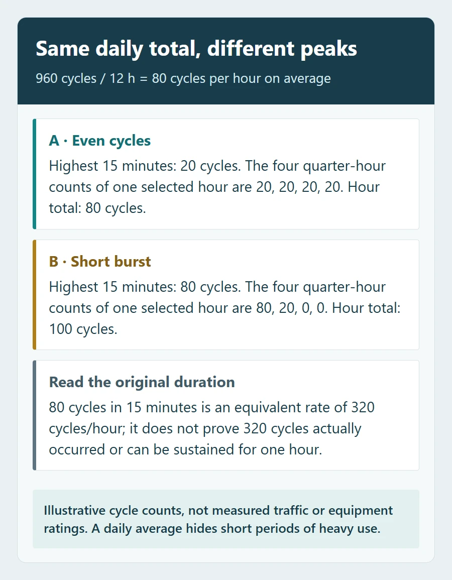
Arithmetic example, not measured traffic or a product rating: two barriers each complete 960 cycles over a 12-hour operating day. Both average 80 cycles per operating hour. At site A, the highest 15-minute count is 20; at site B, it is 80. Site B’s brief peak is four times as intense even though the daily totals match.
Multiplying 80 cycles in 15 minutes by four gives an equivalent rate of 320 cycles/hour. Report the original 80 cycles in 15 minutes as well: this conversion does not mean that 320 cycles occurred, or can be sustained, throughout an hour. Send the actual sequence and its duration to the supplier rather than comparing only converted averages.
A workload worksheet for the site operator
Complete one copy for each barrier. Enter observed values where available and mark forecasts clearly. Blank cells are working fields for your site survey.
| Record | Your site value | What to include |
|---|---|---|
| Barrier and observation period | ________ | Lane ID, direction, dates and operating hours |
| Counting convention | ________ | Complete cycles or individual movements; counter conversion |
| Daily complete cycles | ________ | Typical and busiest day, with extra operations noted |
| Busiest 15 minutes | ________ | Actual count and timestamps |
| Busiest continuous hour | ________ | Actual count, rather than a short burst multiplied up |
| Longest busy sequence | ________ | Duration, movement spacing, open holds and available pauses |
| Forecast change | ________ | Growth, events, changed lane allocation or operating hours |
Read duty cycle, operating frequency and life separately
| Specification | Question it helps answer | What still needs confirmation |
|---|---|---|
| Cycles per hour | How frequently can the specified assembly repeat its cycle? | Cycle definition, arm and accessories, speed, conditions and permitted duration |
| Duty cycle or use frequency (%) | What operating/rest pattern is permitted under the manufacturer’s definition? | Numerator, measurement window, load, temperature and required pauses |
| MCBF: mean cycles between failures | What average failure-interval figure is being declared? | Failure definition, test population, configuration, maintenance and exclusions |
| Rated or design life in cycles | What durability claim applies, and to which part or assembly? | Test method, replacement parts, conditions and whether it is a design target or another defined measure |
| Warranty | What support or remedy is contractually provided? | Term, cycle limits if any, exclusions and service responsibilities |
Keep the original wording when comparing quotations. A spring-life claim, motor-life claim and whole-machine MCBF figure do not have the same scope. For example, Nice’s barrier systems brochure states a nominal-torque condition for operating-frequency figures and separately describes balancing-spring durability. These are that manufacturer’s product declarations, not SHUNJIE performance figures.
A “100%” or “continuous use” statement must be read with the manufacturer’s conditions. It does not mean unlimited cycles per hour, unlimited lane throughput or maintenance-free service. Equally, a percentage such as 50% should not be translated into “12 hours of operation per day” without the specified measurement window and rest pattern.
A timing example explains why the definition matters
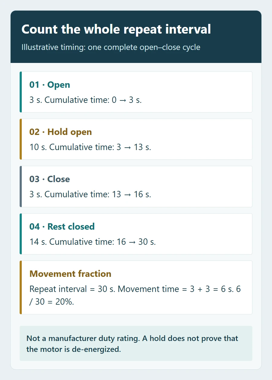
Suppose an illustrative sequence uses 3 seconds to open, holds open for 10 seconds, uses 3 seconds to close and waits closed for 14 seconds. It repeats every 30 seconds. The moving portion is 6 ÷ 30 = 20%. That is a description of this example’s motion timing, not proof of a manufacturer’s 20% duty rating.
The drive’s energized time may differ from its moving time. A different speed setting, reversal, load or measurement window can change the comparison. Ask the supplier which definition applies before converting movements into a percentage.
Confirm the complete arm and drive configuration
Compare the operator, arm, balancing arrangement and accessories as one assembly. A cabinet name or motor voltage alone is not enough. Give the supplier the actual arm type and length, any skirt or advertising panel, lighting, approved supports and intended opening and closing settings.
Also describe the ambient temperature during the busy period, direct sun exposure, ventilation conditions and power supply. Ask whether the proposed operating frequency changes under those conditions. An allowed operating-temperature range does not, by itself, establish that the highest frequency is available throughout that range. Obtain any applicable limits or derating information for the exact assembly.
SHUNJIE’s barrier gate range presents different drive and arm options. Send the workload worksheet with the proposed arm and site conditions so the recommendation can address the complete configuration. A headline cycle-life claim should remain separate from the confirmation of your required peak operating pattern.
Request a written workload confirmation before ordering
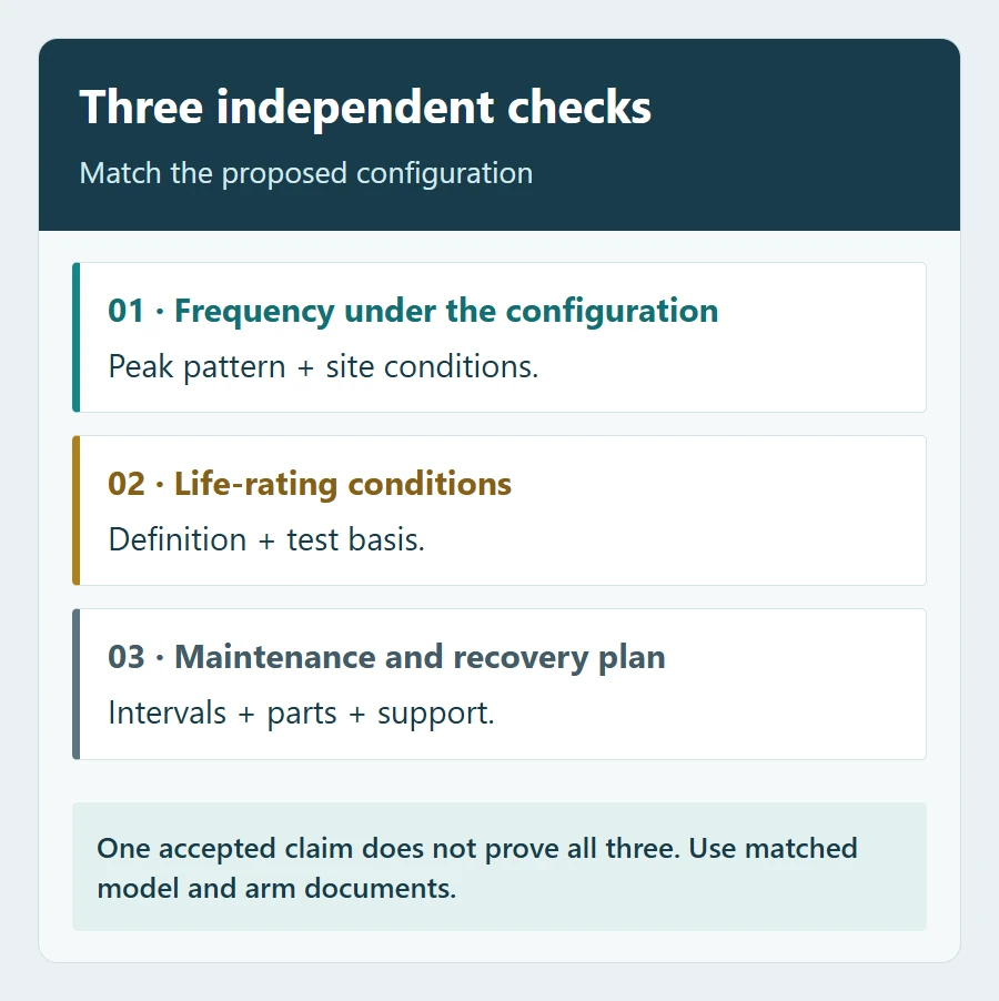
Attach the same workload record to each quotation request. Ask for a response against these points, with the supporting document and revision identified:
- Assembly: exact operator, controller and relevant firmware, arm, balancing components, accessories and speed settings.
- Operating capability: permitted cycles/hour or duty definition, measurement window, maximum continuous busy period and any required recovery pauses.
- Site conditions: confirmation against the supplied temperature, exposure, supply and load information, including applicable restrictions.
- Life claim: the component or complete assembly covered, measurement method, failure criteria and assumed maintenance or replacement parts.
- Service plan: calendar and cycle-count maintenance triggers, counter interpretation, wear parts, local support and fault-recovery instructions.
Ask the supplier to identify any mismatch and propose a documented alternative. Resolve missing evidence before approving a configuration. Do not fill the gap with a generic rule such as “all brushless barriers are heavy duty.” The parking access control RFQ template can help keep the wider supply and acceptance responsibilities comparable.
Check the agreed peak pattern during commissioning
A short opening demonstration cannot establish suitability for a sustained busy period. Agree a controlled commissioning plan with the supplier and competent installer, using the approved configuration and its documented operating limits. Keep the lane controlled and protective devices active; do not bypass detection or force repeated movement after a fault.
Record the configuration, conditions, cycle count, counting convention, timing and duration. Check completion of commands, positioning, unexpected pauses, alarms and any prescribed recovery behaviour. Use the manufacturer’s approved diagnostic method for temperature or drive status where available. If an unexpected protective stop or abnormal movement occurs, stop the trial and have the cause assessed before continuing.
A successful commissioning run supports acceptance of the agreed operating scenario. It does not prove a multi-million-cycle life claim or every seasonal condition. Where the required environment cannot be reproduced, document the supporting evidence and the remaining seasonal check.
Plan maintenance around actual use
Use the exact model’s maintenance instructions, including both calendar and cycle-count conditions where specified. A busy barrier reaches a count-based service point sooner than a lightly used one. Retain cumulative counts and service records, including counter resets and the parts replaced.
Ask who will respond if the barrier develops irregular movement, unusual noise or repeated protective stops, and how access will be managed during service. Internal adjustment and repair belong with competent personnel following the equipment instructions.
For a configuration review: send SHUNJIE the per-barrier worksheet, arm type and length, accessories, operating settings, environmental conditions and required support arrangement. The useful selection is a documented match between the machine and its workload.
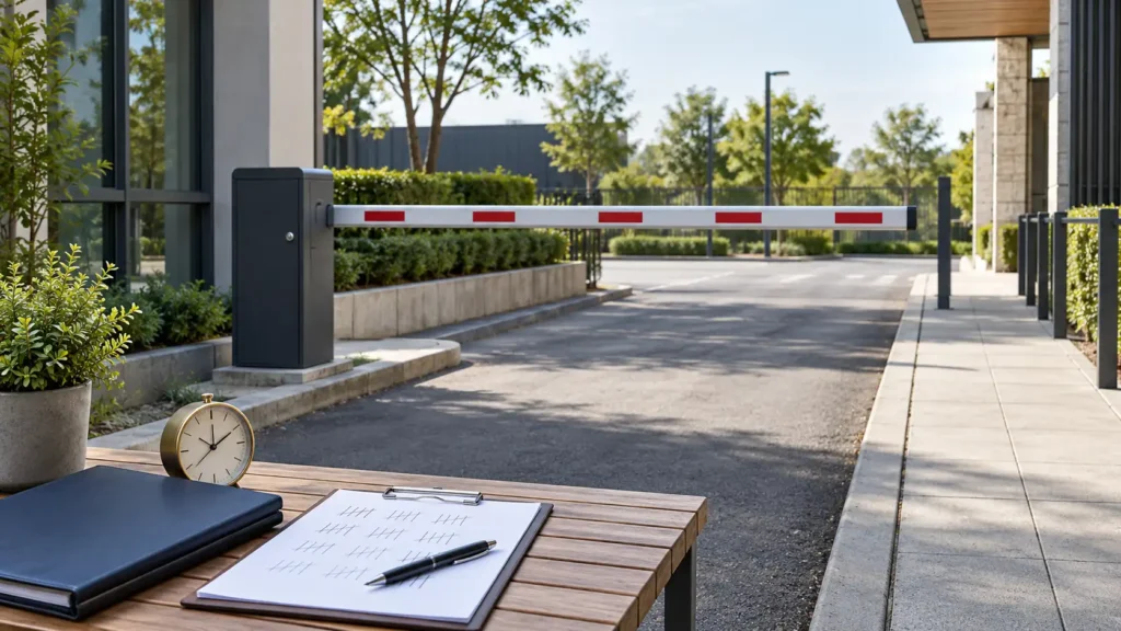
Featured image: AI-generated planning scene with generic equipment and an illustrative tally sheet. It is not a SHUNJIE project, measured traffic record or duty-cycle test.
Featured image: AI-generated planning scene with generic equipment and an illustrative tally sheet. It is not a SHUNJIE project, measured traffic record or duty-cycle test.