Parking entrances, offices, hospitals and factories need plate images that remain usable in everyday conditions. A clear demonstration in good light is not a site acceptance test. This guide explains how camera geometry, image scale, exposure and illumination work together, and how to verify the result without treating another manufacturer’s settings as universal Shunjie specifications.
Why parking LPR is an engineering task
Recognition software needs visible character detail. Motion blur, overexposure, a plate that is too small or an obstruction can remove the information it needs. Consider the whole lane: changing speeds, wet plates, headlights, morning and evening sun, dirty lenses, nearby vehicles, the barrier and pedestrian routes. Adjusting software alone cannot reliably restore detail that was never captured.
Checks before mounting
- Geometry and scale: define the reading zone, mounting position and expected vehicle paths. Check horizontal and vertical viewing angles and the plate width in pixels at the near and far limits.
- Exposure and lighting: use the chosen model’s plate-capture profile where available. Confirm that shutter, gain, infrared illumination and day/night changes suit moving plates.
- Reliability: test expected plate formats and vehicle types in representative conditions. Plan assistance or a second credential for missed or uncertain reads.
1. Motion blur and reflective plates
Speed, angle and shutter time
When a vehicle approaches nearly along the camera’s viewing direction, its plate mainly grows in the image. At an oblique angle it also moves across pixels. Longer exposure can then smear characters. Higher speed or a less favorable angle may require a shorter exposure, which in turn collects less light.
For illustration, the Axis plate-capture white paper gives the following maximum shutter times at 30 km/h. These are reference examples from that document, not tested settings for Shunjie cameras or a substitute for the selected camera’s instructions.
| Camera-to-travel angle | Reference maximum shutter time at 30 km/h |
|---|---|
| 10° | 9.7 ms |
| 20° | 4.9 ms |
| 30° | 3.4 ms |
If shortening exposure makes the plate too dark, review the angle, vehicle speed and suitable illumination. Increasing image brightness or gain alone can add noise or saturate a reflective plate without fixing motion blur.
Retroreflection and infrared alignment
Many registration plates return a substantial part of incident light toward its source. A separate IR illuminator therefore needs an appropriate position close to the camera and a beam aligned with its viewing zone, according to the equipment instructions. A distant or poorly aimed source may light the road while providing little useful plate contrast. Check both reflective and other plate types expected at the site.
2. Angle, distance, image scale and focus
2.1 Horizontal and vertical angles
Minimize unnecessary oblique viewing while preserving a safe, practical installation. Height, sideways offset and reading distance all affect the angle; software perspective correction is not a reason to ignore geometry. Confirm the chosen recognition system’s limits for local plate layouts rather than combining maximum angles from unrelated cameras.
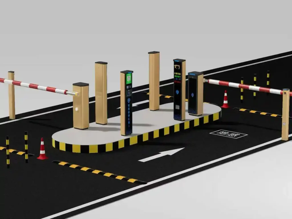
At a controlled gate, a defined stop line can make the reading zone predictable. Free-flow or turning lanes may need a different position or more than one camera. Lane markings and suitable traffic-calming measures can help, but any bollards, humps or lane changes must preserve emergency access, accessibility and safe vehicle movement.
2.2 Capture distance and time in view
The useful distance is the range over which the plate is large, sharp, illuminated and visible enough to read. It is not simply the lens’s maximum zoom distance. A faster vehicle spends less time in that range. Check the recognition engine’s actual processed frame rate and detection behavior, not only the camera’s advertised video frame rate.
The same Axis reference lists 4 m, 7 m and 11 m as example minimum capture distances for 10, 30 and 50 km/h respectively, based on an assumed detection time of 0.2 seconds. Treat these as an explanation of the relationship, not universal design distances. Nighttime IR reach, plate format and software processing can change the usable zone.
If vehicles leave the zone before a usable read, assess a longer readable zone, safe speed management or supported processing changes. Verify the whole change: increasing distance can make plates smaller and darker, while increasing processing demand can reduce system capacity.
2.3 Plate pixels before camera megapixels
Obtain the recognition engine’s required plate size and supported stream settings. Choose the reading zone, then lens and field of view so the local plate format meets that requirement throughout the zone. Pixel targets differ with character size, plate layout and software; figures from another pipeline are not interchangeable.
A wider view includes more surroundings but reduces the pixels available for each plate. Higher resolution may help only if the lens resolves the detail and the processor can analyze the stream in time. Measure plate width in recorded frames; do not use digital enlargement as evidence that missing detail has been recovered.
2.4 Depth of field
Check focus over the full zone where plates actually appear, including different vehicle heights and day/night operation. Focus at one parked vehicle is insufficient. Aperture, focal distance and lens choice affect depth of field; restricting the aperture can improve the focused range while reducing available light. Use the camera’s supported focus procedure and confirm the result with moving vehicles.
3. Night capture: IR, gain and WDR
3.1 Illumination and exposure
Short exposure limits blur but reduces collected light. A general surveillance IR-distance rating may use settings different from plate capture. Verify the selected model’s plate-capture rating, beam coverage and power requirements. Do not assume that a brighter illuminator automatically improves the image: beam shape, plate reflectivity, distance and saturation all matter.
Where night capture is inadequate, assess supported illumination, improved alignment, a better reading-zone position or appropriate speed control. After each change, test near and far vehicles and confirm that the beam does not create new reflections or interfere with neighboring lanes.
3.2 Maximum gain and overexposure
A reflective plate can become a bright rectangle with unreadable characters while the background remains dark. Review maximum gain, exposure and IR intensity together. Start from the model’s documented profile, then compare real vehicles at several distances. An exact dB value from another camera or illuminator is not a universal parking setting.
Do not judge success by an attractive overview image alone. Preserve character contrast, and use a separate overview stream or camera where the system supports it and the project needs wider context.
3.3 WDR and moving plates
Wide dynamic range can improve general surveillance, but some implementations combine exposures in ways that create artifacts on moving plates. Follow the model’s plate-capture guidance. Where WDR is disabled by that profile, do not enable it merely to brighten the background; where a suitable technique is supported, validate it with actual motion, glare and night traffic.
3.4 Establishing a baseline
Record the camera model, firmware, lens, stream resolution, processed frame rate, shutter limit, gain limit, IR mode and WDR choice. Begin with supported manufacturer settings rather than copying a generic 1/500-second or gain preset. Change one relevant factor at a time, save representative permitted samples and document why the final settings were accepted.
4. Weather, glare, dirt and obstruction
4.1 Sun position and glare
A lane may work at midday and fail when low sun enters the lens. Consider seasonal sun position and nearby lights, not just the installation hour. Review mounting direction, approved shading and the reading zone. Test the actual difficult periods after adjustment. More IR or a tighter view is not a guaranteed cure for direct glare.
4.2 Rain, fog, snow and frost
Poor weather can reduce visibility and contrast or obscure the plate itself. A shorter readable distance or suitable illumination may help in some conditions, but cannot make a covered plate readable. Test the conditions reasonably expected at the site and define a fallback such as an authorized badge, QR route or operator assistance. Do not promise an all-weather recognition percentage without representative evidence.
4.3 Dirt, water spots and insects
Road spray, exhaust deposits, water spots and insects can gradually degrade the lens or illuminator window. Set inspection and cleaning intervals according to the location and equipment instructions. Use declining read quality as one maintenance trigger, while checking whether traffic, lighting or configuration changes caused the decline. Record cleaning and subsequent results.
4.4 Keeping plates visible
Inspect the line of sight for the barrier arm, columns, bollards, tow hitches, bicycle racks, plate frames and following vehicles. Check the plate before and during barrier movement and across expected vehicle heights. Mark the stopping position to match the reading zone. If changing height or offset, reassess angle, focus and light rather than solving one obstruction by creating another problem.
Separate pedestrian routes appropriately and assess safeguarding independently. A camera read is an access input, not proof that the barrier movement area is clear or safe for people. Traffic-calming and spacing measures must suit the physical site and be assessed by competent installers.
5. Commissioning and troubleshooting
5.1 A repeatable commissioning sequence
- Confirm the lane plan, safe mounting location, cable routing and supported power/network arrangements.
- Mount and aim the camera and any approved illuminator at the defined zone.
- Verify plate size in the actual configured stream at the zone limits.
- Focus and check the usable depth of field with representative vehicles.
- Set the supported exposure profile, shutter/gain limits, IR and WDR behavior.
- Test daytime traffic, turning vehicles, queues and difficult sun positions.
- Test at night with headlights, reflective plates and near/far vehicles.
- Document weather limits, outages and the agreed assistance or credential fallback.
- Collect permitted samples, compare with the acceptance criteria and save the approved configuration.
- Assign monitoring, cleaning, fault response and retesting after changes.
5.2 What to measure at acceptance
Report by lane and time period: vehicles observed, usable plate images, correctly read plates, missing/unreadable events and manual interventions. Define the denominator and treatment of vehicles without a visible plate. For payment or enforcement, also assess correct entry-exit matching and disputed decisions. A camera recognition rate is not the same as successful passage or correct billing.
Include the local vehicle and plate mix, traffic peaks and supported operating conditions. Record unresolved limits and assign corrective work. Keep evidence only as permitted for the purpose, with appropriate access and retention controls.
5.3 Symptoms, checks and corrective actions
| Symptom | What to check | Possible corrective action |
|---|---|---|
| Blur in daylight | Exposure time, angle and vehicle speed | Use supported shorter exposure, improve geometry or manage speed; recheck light. |
| Bright unreadable plate at night | Plate saturation, gain, IR and distance | Adjust supported exposure/gain/illumination settings and retest near and far. |
| Failure at sunrise or sunset | Direct sun, flare and exposure changes | Review direction or approved shielding and retest at the difficult hour. |
| Misses in heavy traffic | Occlusion, following distance and processing load | Improve separation or coverage and verify supported processing settings. |
Documentation for handover
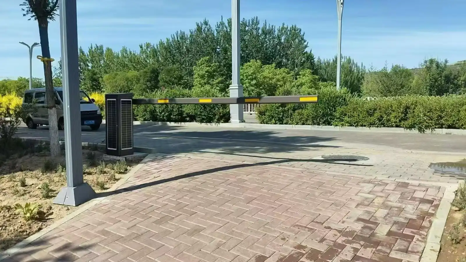
Keep a lane plan showing the camera, illumination, stop line and capture zone; record near/far plate samples and the accepted configuration. If diagrams are used, label them as installation aids, not measured performance evidence. Actual site photographs should describe what is visible without claiming an accuracy result they cannot prove.
Frequently asked questions
Is resolution or placement more important?
Both must meet the recognition system’s requirements. More pixels cannot recover a blocked, badly blurred or saturated character. Establish suitable placement and a readable plate size, then verify processing capacity at the chosen resolution.
Should parking LPR use WDR?
Follow the selected model’s plate-capture guidance and test moving vehicles. Some WDR methods introduce artifacts; other models provide a suitable capture mode. Do not make a universal on/off rule across all cameras.
Why do results worsen in rain or snow?
Visibility, contrast, reflections and contamination can change, or the plate may become physically covered. Inspect recorded frames to distinguish these causes, maintain the equipment and use the agreed fallback when a usable image cannot be obtained.
Technical reference and project support
The Axis license plate capture white paper explains the cited reference examples. They are not Shunjie product specifications. For a project review, send the lane plan, expected speed, local plates, lighting and proposed equipment through our contact page. Placement guidance, supported settings and volume pricing require confirmation for the actual configuration.