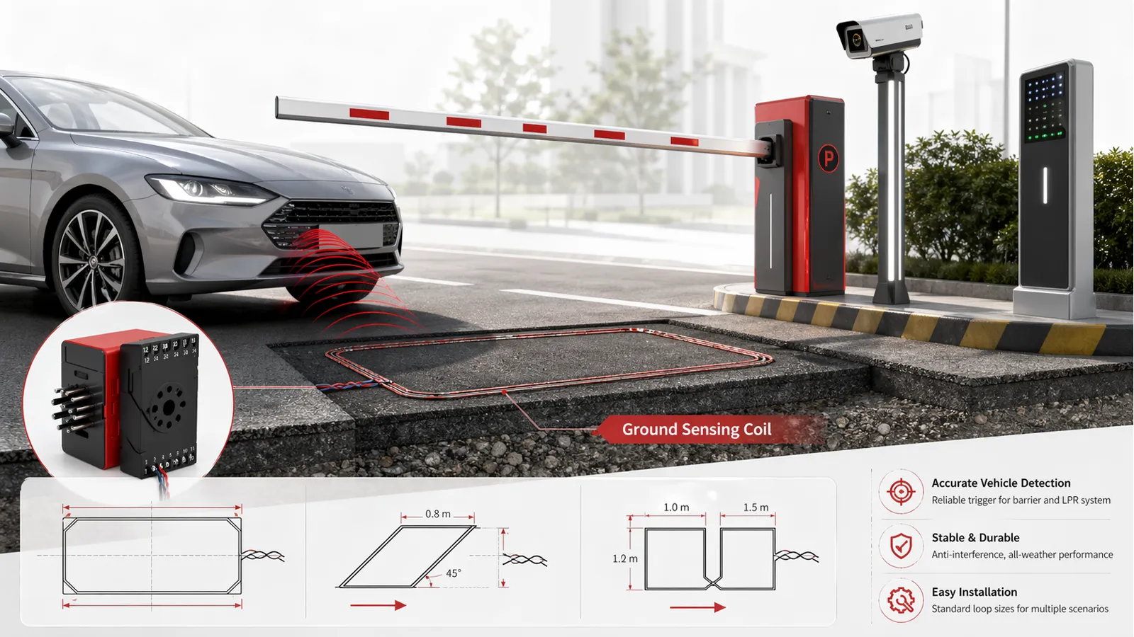
A ground sensing coil plays a critical role in a license plate recognition barrier system. It detects the presence and movement of vehicles, helping the barrier gate respond accurately and preventing the arm from closing on a car. In parking lots, gated communities, commercial entrances, and smart access control projects, a properly installed loop coil is essential for stable and safe operation.
This guide explains how to install a ground sensing coil correctly, including site requirements, installation methods, coil turns, output lead rules, and embedding steps.
Why the Ground Sensing Coil Matters
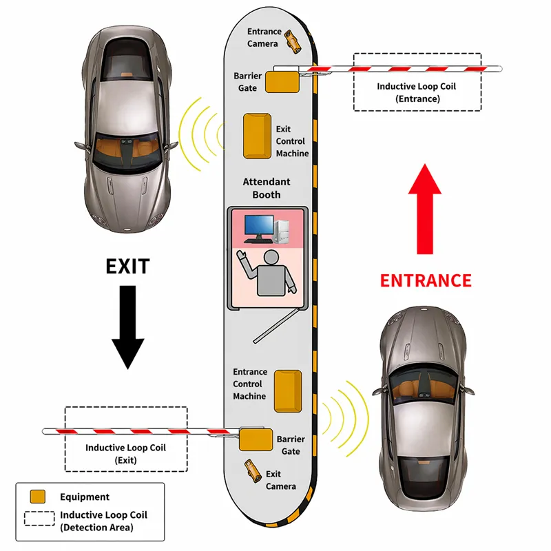
In an LPR parking system, the ground sensing coil works together with the barrier gate and controller to identify when a vehicle is approaching, passing, or waiting in the lane. Its most important function is anti-crush protection. If the coil does not detect vehicles accurately, the barrier may open or close at the wrong time, affecting both safety and traffic efficiency.
For that reason, correct installation is just as important as choosing a reliable barrier system.
1. Installation Requirements
Before cutting the pavement and laying the coil, check whether the installation area meets the following requirements.
Basic requirements
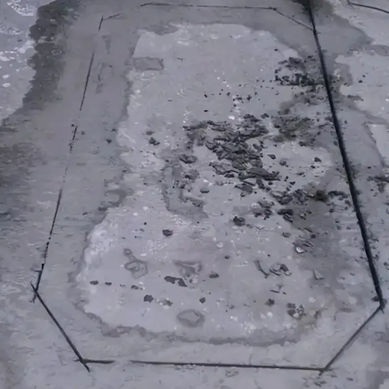
- Avoid damaged pavement. On concrete surfaces, do not place the loop over existing cracks.
- There should be no large metal objects within 50 cm of the coil, such as manhole covers or drainage grates.
- There should be no high-voltage power lines or strong electrical interference sources within 1 meter of the coil area. The interference voltage affecting the loop should not exceed 2 mV.
- There should be no magnetic materials, such as magnets, within 1 meter of the coil.
- The spacing between two separate coils should not be less than 1.3 meters. If two coils are connected to the same vehicle detector, the spacing should be at least 50 cm to prevent interference.
- If the loop is installed above reinforcing steel in reinforced concrete, the coil should be at least 50 cm above the steel bars, and the coil turns should be increased by 1 to 2 turns.
- Before laying the cable, make sure the slot is completely cleaned. Small stones or debris left in the groove can damage the cable insulation when vehicles repeatedly pass over it.
Quick reference table
| Item | Recommended Requirement | Purpose |
|---|---|---|
| Distance from large metal objects | At least 50 cm | Reduce signal interference |
| Distance from high-voltage lines | At least 1 m | Prevent electrical noise |
| Distance from magnetic objects | At least 1 m | Maintain stable detection |
| Spacing between coils | At least 1.3 m | Avoid cross-interference |
| Spacing if sharing one detector | At least 50 cm | Reduce mutual influence |
| Slot condition | Clean and dry | Prevent cable damage |
2. Ground Sensing Coil Installation Methods
Different project conditions require different loop layouts. The most common installation methods are rectangular, 45-degree angled, and figure-eight layouts.
2.1 Rectangular installation
Rectangular installation is the most common and universal method.
Normally, the detection loop should be laid in a rectangular shape. The two longer sides should be perpendicular to the direction of vehicle travel. The recommended spacing between the long sides is 0.8 to 1 meter. The actual loop length depends on the lane width, and both ends are usually 0.3 to 1 meter narrower than the road width.
Important note:
When cutting the slot, the four corners should be chamfered at 45 degrees rather than cut as sharp right angles. This helps prevent cable damage and reduces the risk of pavement edge breakage.
2.2 45-degree angled installation
When smaller vehicles such as motorcycles or bicycles also need to be detected, the coil can be installed at a 45-degree angle to the direction of travel. This layout can improve sensitivity in special applications.
2.3 Figure-eight installation
When the road surface is wide, usually more than 6 meters, and vehicles have a relatively high chassis, a figure-eight layout can be used. This method spreads the detection area and improves sensitivity.
Installation method comparison
| Installation Type | Recommended Use | Main Advantage |
|---|---|---|
| Rectangular | Standard parking lanes | Simple, reliable, widely used |
| 45-degree angled | Motorcycle or bicycle detection | Better sensitivity for smaller vehicles |
| Figure-eight | Wide lanes or high-chassis vehicles | Broader detection coverage |
3. Number of Coil Turns
To ensure the vehicle detector works properly, the loop inductance should generally be kept between 100 μH and 300 μH.
When the target inductance remains the same, the number of coil turns depends on the perimeter of the loop. In general, the smaller the perimeter, the more turns are required.
Recommended turns by loop perimeter
| Loop Perimeter | Recommended Turns |
|---|---|
| Less than 3 m | 6 turns |
| 3 to 6 m | 5 turns |
| 6 to 10 m | 4 turns |
| 10 to 20 m | 3 turns |
| More than 20 m | 2 turns |
Important note on actual installation
The table above is for reference only. In real projects, buried metal objects such as steel bars, underground cables, drain covers, or pipelines may significantly affect the actual inductance value.
For this reason, installers should use an inductance meter during construction and adjust the number of turns based on the measured value. The final goal is to keep the loop inductance within the correct working range of 100 μH to 300 μH.
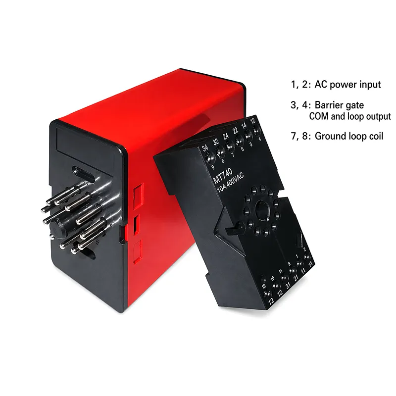
4. Output Lead Wire Requirements
The output lead wire connects the loop coil to the vehicle detector. Improper lead wire handling can introduce interference and reduce detection performance.
Lead wire rules
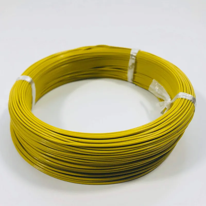
- Leave enough cable length when winding the loop so it can reach the detector without any intermediate joints.
- After winding the coil, the output lead wire must be tightly twisted. The recommendation is at least 20 twists per meter.
- The output lead wire should generally not exceed 5 meters. As lead length increases, loop sensitivity decreases, so the wire should be kept as short as possible.
Why twisting matters
If the output lead wire is not twisted tightly, it may pick up interference from the surrounding environment, causing unstable inductance values and unreliable vehicle detection.
5. How to Embed the Coil in the Ground
The embedding process starts by cutting a slot into the road surface using a road cutter. This part of the installation must be done carefully to protect both the pavement and the cable.
Standard slot dimensions
- Slot width: 4 to 8 mm
- Slot depth: 30 to 50 mm
- Corner treatment: 45-degree chamfer
- Lead-out groove: One additional slot should be cut from the loop to the roadside or control box
Embedding steps
Step 1: Cut the slot
Cut the groove in the required shape based on the chosen installation method.
Step 2: Chamfer the corners
Chamfer all four corners at 45 degrees to reduce pressure on the cable and prevent sharp-angle damage.
Step 3: Clean the slot thoroughly
Remove all dust, stones, water, and other debris. The slot must be clean and dry before cable installation.
Step 4: Lay the coil cable
Place the cable neatly at the bottom of the groove. Keep the wire straight, but do not pull it too tightly.
Step 5: Route the lead wire
After winding the loop, route the tightly twisted output lead through the lead-out groove.
Step 6: Test the inductance
Use an inductance meter during installation to confirm that the loop inductance is within the required range of 100 μH to 300 μH.
Step 7: Adjust if needed
If the measured inductance is outside the proper range, increase or reduce the number of coil turns.
Step 8: Seal the groove
Once testing is complete, seal the groove using suitable filling material to protect the wire from water, pressure, and long-term wear.
Embedding checklist
| Item | Standard |
|---|---|
| Slot width | 4 to 8 mm |
| Slot depth | 30 to 50 mm |
| Corner type | 45-degree chamfer |
| Lead wire twist rate | At least 20 twists/m |
| Lead wire length | Not more than 5 m |
| Target inductance | 100 μH to 300 μH |
6. Common Mistakes to Avoid
Even when the loop looks properly installed, small construction mistakes can cause future problems. Here are some of the most common issues to avoid:
- Installing the loop too close to manhole covers, drainage grates, or buried metal
- Cutting the slot across cracked or damaged pavement
- Leaving gravel or debris inside the groove
- Using output leads that are too long
- Failing to twist the output leads tightly
- Ignoring the effect of reinforcing steel or underground utilities
- Skipping inductance testing during installation
- Cutting sharp 90-degree corners instead of 45-degree chamfers
Avoiding these problems will improve both detection stability and long-term service life.
Conclusion
A ground sensing coil is a key part of a license plate recognition barrier system, especially for reliable vehicle detection and anti-crush protection. To achieve stable performance, installers must select the right location, choose the correct loop layout, control the number of turns, handle the lead wire properly, and verify the final inductance value during installation.
In real parking projects, careful loop construction can make a major difference in system safety, performance, and maintenance costs. A well-installed ground sensing coil helps ensure smooth barrier operation and a better user experience for both installers and end users.
FAQ
What does a ground sensing coil do in a parking barrier system?
It detects vehicle presence and movement, allowing the barrier gate to operate safely and accurately.
What is the most common loop installation method?
Rectangular installation is the most widely used method for standard vehicle lanes.
What inductance range should the loop have?
The recommended working range is usually 100 μH to 300 μH.
Why should the output lead wire be twisted?
Twisting reduces interference and keeps the loop signal stable.
How deep should the installation slot be?
The groove is generally cut to a depth of 30 to 50 mm.
What happens if the loop is installed too close to metal objects?
Nearby metal can interfere with the magnetic field and cause inaccurate detection.